LoRa Remote Relay
Summary
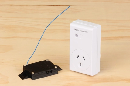
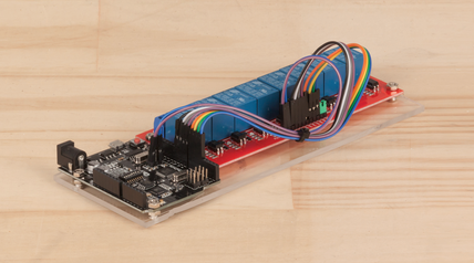
We are very excited to get the chance to play with our new LoRa Shields, and test just how far we could get a signal using LoRa technology. With one of our tests, we were able to get a signal to travel about 200m, including through the corrugated iron of the warehouse and the concrete office building. We set about building a practical project that would make best use of the technology. The LoRa Remote Relay is basic- four buttons at one end and four relays at the other end. It also has LED's next to the buttons, so unlike other remote relay systems, there is feedback that the relays are operating as commanded.
Table of Contents
Future Improvements
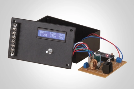
The success of a project like this is using it in a real world application. We've heard of a few people using remote relays to control motorised gates. The advantage of the LoRa Remote Relay in this case is that the actual position of the gate could also be monitored and fed back to the transmitter unit, so that you could not only know that the motors are working, but that the gate has reached its endpoint. Or you could use it for remote pump operation, and also feed the data about tanks levels back to the user.
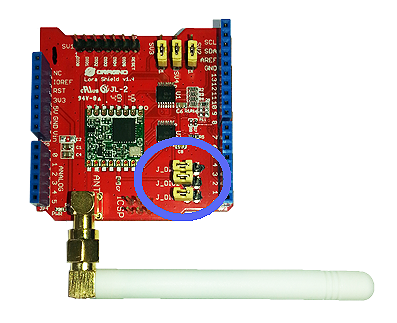
The sketches use the basic default settings for the shield. You can experiment with some of the settings inside the library. These are documented here: https://github.com/sandeepmistry/arduino-LoRa/blob/master/API.md. You may need to make sure that both transmitter and receiver use the same parameters, otherwise they may not 'hear' each other. The testing we did was in an urban area around concrete and corrugated iron, and longer ranges should be achievable with clear line of sight. Increasing the spreading factor and coding rate may also improve signal robustness at the expense of transmission speed.
Of course, this is just one use of the LoRa Shield- many systems that work with serial data can be modified to work with LoRa- the data just needs to be assembled into packets to be sent. You could even have multiple sensors in the field feeding data back to a central receiver.
Similar projects you may be interested in